

3D Printed Linear Motion (MVMT 92) : 17 Steps (with Pictures) - woodallmanower49
Introduction: 3D Printed One-dimensional Motion (MVMT 92)
With this handy gadget, you can turn rotary motion into bilinear motility with facilitate! Using some skateboard bearings, car screws, and 3D written parts, the machine comes together very fast and can comprise used for all kinds of machines or robots.

507 Mechanical Movements is an encyclopedia of rough-cut mechanisms from the 1860's that serves as a sainted reference for this kind of thing. This mechanism is bases on number 92, "Ordinary Crank Apparent motion".This is passing to be along task, so if you've got a specific chemical mechanism you'd ilk Maine to make believe, sense free to make a request in the comments!
I utilized mine to make a machine that endlessly draws a sine wave. Imaging trying to bash this by hand- it's a good time to live alert!

Step 1: Tools + Materials
- Fusion 360
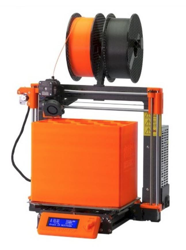
- 3D Pressman
-
I habituate a Prusa I3Mk3S for just about everything. It's the best smack for your buck, in my opinion- all right made, 3D printable replacement parts, accurate and reliable.
-
- 3D Print Filament
- I used Matte Fiber HTPLA from Proto-pasta for this project, merely pretty much whatsoever filament volition bring. I corresponding this squeeze because the finish looks genuinely in effect.
- I used Polymaker Polyflex for the belt. It worked awhile but flexible out eventually, I'll belik redo this project with a big o-ring or a manufactured belt.
- 608ZZ Skateboard Bearings: There are piles of types to select from, but whatsoever cheap ones will do. Don't worry to a fault some about "spin clock time" as you would with fidget thread maker.
- M3 Screws + Nuts: You could use any screws and haywire round this size, but I see these work well for small 3D written mechanical projects.
- Receipt Paper: $4 on Amazon.
Unification 360 is free and it's awesome. I practice it for everything I design and fabricate.
Student / Educator License (regenerate free every 3 years)
Hobbyist / Startup (renew unloosen yearly)
Pace 2: Invention / 3D Modeling
The video above is a step aside step demonstration of the modeling procedure. The steps that follow describe what's in the video.
The f3d file in this abuse is the Fusion 360 archive that you can download and upload to a stick out in Fusion.
Step 3: Insert Bearing + Create Base

First, get a bearing into the canvas. Go to Insert>John Bach McMaster Carr Ingredient, hunt "608 bearing", and sail to the ware item of the low i you find. Make a point file type is exercise set to 3D STEP and select Save. The bearing will go in American Samoa a new component which you can revolve around 90º to make it vertical.
Incoming, Foregather>Newly Component to preserve your designing organized.
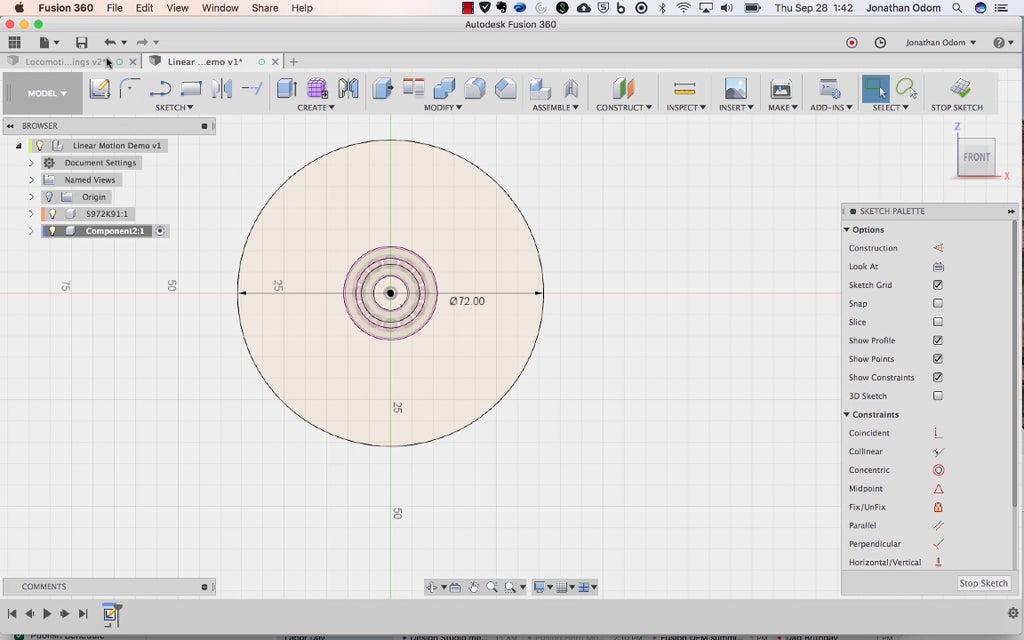
Make over a chalk out on the Front plane of the canvas and Sketch>Project/Include>Project to incur the outline of the bearing into the sketch (be sure selection filter in that command is set to Bodies).
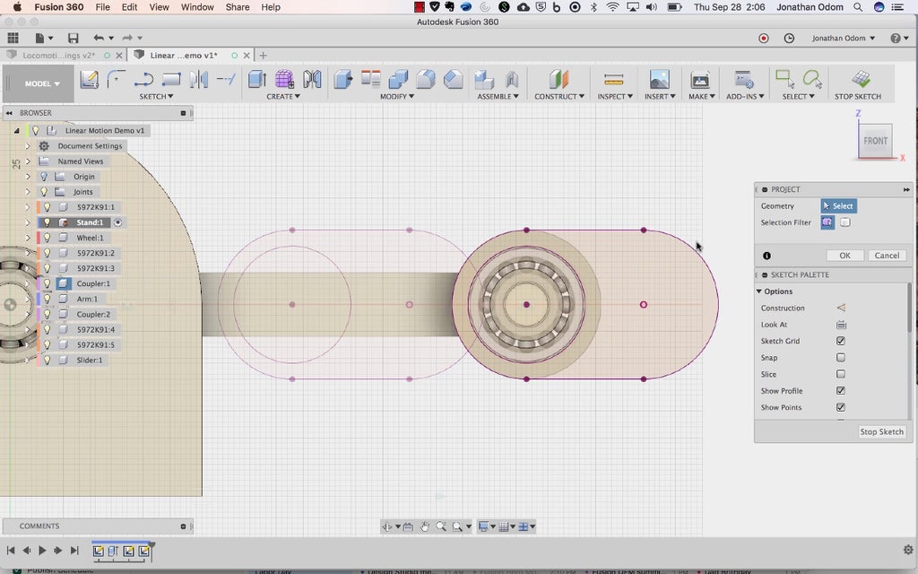
With the supporting perimeter projected, make a Sketch>Circle>Center Diameter Circle on the center of the canvas. Type in 72mm for the diam.

Make a Study>Rectangle, then Sketch Palette>Constraints>Tangent to make terzetto of the lines tan to the set As seen above.

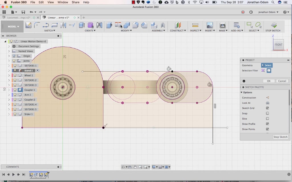
Create>Extrude the profiles as shown above. If you made a new part before you started your sketch, leave the Operation as New Body, otherwise change the Operation to Current Portion.
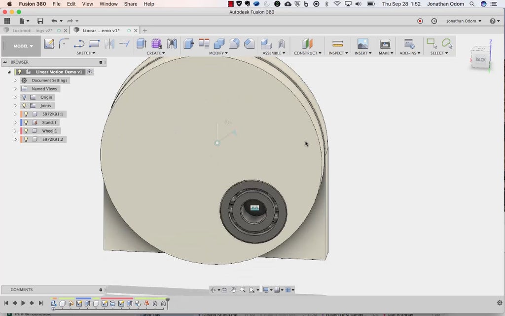
Whole tone 4: Create a Wheel

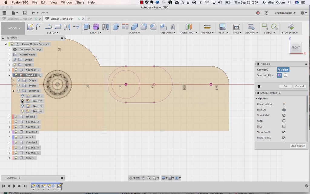
Activate the top take down ingredient (right-click>Activate) called Linear Motion Demo at the top of the web browser in the screenshot above. Assemble>New Portion to keep things organized, then make a new sketch on the Top plane of the sail.
Study>Project/Include>intersect and click on the inner ring of the heading.

Now you're expiration to draw a cross-section of a wheel that you'll use to revolve a 3D shape. Draw a centerline by clicking along the model origin point and clicking somewhere to the left as shown above. Make foreordained the logical argument is 90º.

Sketch>Offset this line by 36mm (half of 72mm).

Pull down a line that's perpendicular to the deuce other lines somewhere off to the left as shown.

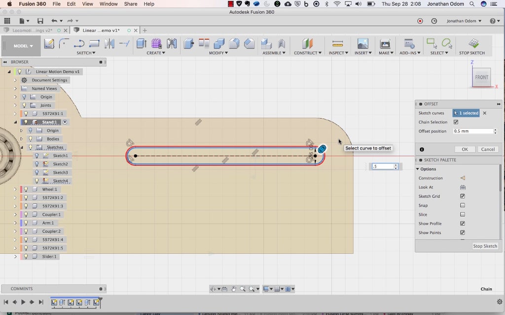
Draw a cloud profile that looks something like what's shown above. There needs to be a shoulder against the bearing (shown above with a gap between them) and a kinked line to offset the face of the wheel.

Employ Sketch>Sketch Attribute to get everything in place. The inside line is offset by .5mm to provid some space between the urge on convulsion parts, the shoulder kink is set to 120º (this could comprise a right lean and it would still lic, this just gives you a little Thomas More material for strength), the inside face of the wheel is 1.5mm from the face of the productive, and the thickness of the wheel is 7mm (same arsenic a heraldic bearing).
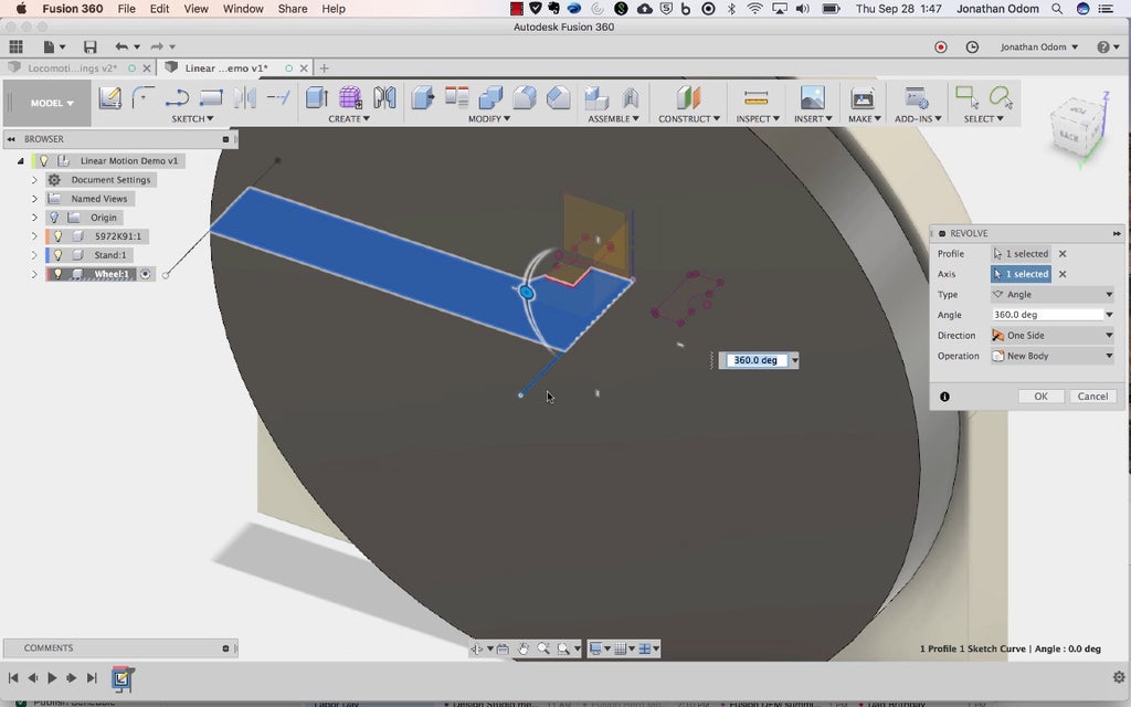
Create>Revolve with the profiles you just created, using the center line as the bloc of rotation. Make a point it's set to full rotation operating room 360º. If you'rhenium already active in your new component, New Organic structure is pulverized for the Surgical operation type.

Create another sketch on the face of the wheel you reasonable made. Draw a center line from the center of the wheel off to the rectify somewhere.

Draw a 22mm circle (diam of the bearing), then Sketch Palette>Constraints>Coincident constrain it to the center line. Draw a upright line to the centerline, then Sketch>Cartoon Dimension information technology so that it's 3mm from the outer edge of the circle. Sketch Pallet>Constraints>Tangent constrain the circle to the vertical line. This will make a point there's decent material on the outside of the wheel to keep from breaking with the bearing is pressed in.

Create>Extrude the circle through the wheel to make a hole for the bearing.

Copy/Paste the bearing component (with top flush component active) so use the point-to-point move option to get the aim on the nose in the justly dapple.
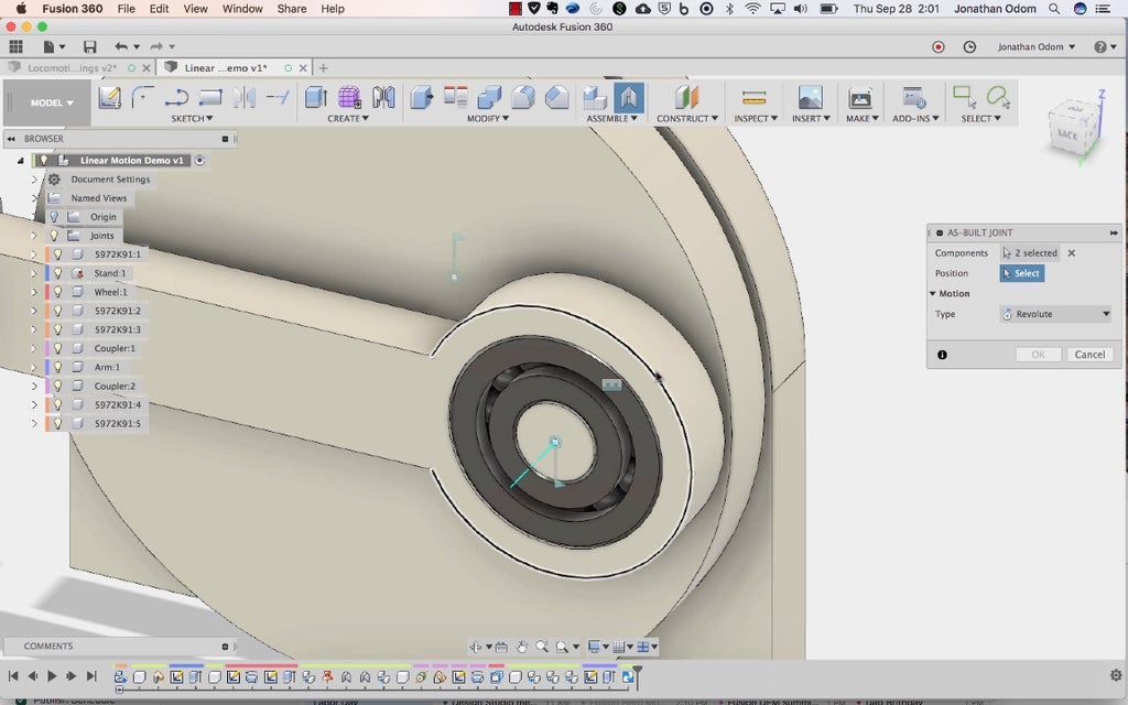
Abuse 5: Stool a Revolute Joint

Now you're going to relieve oneself the first-class honours degree joint. Before you coif that, right-click on the base component in the browser and select Ground. This testament livelihood the base from moving around when you move the joint.

Assemble>As-Built Joint and click on the pedal and the home. For Position, click on any circular edge on the rack Oregon the counterfeit as shown above.

This will make the wheel around turn about the center axis. The bearing ISN't moving because it's not united yet.

Do another As-Built Juncture to connect the bearing to the wheel. This one should be Eccentric: Intolerant.
If you right-click along the first-year revolute joint and select "animate model" you should see the wheel turning with the bearing sledding on for the ride.
Step 6: Make a Coupler

Replicate / Paste the bearing on the roulette wheel and affect it away from the side by 8mm, going away a 1mm breach 'tween them.

Piece>New Component, and then attend Fabricate>Axis Through Cylinder/Conoid to make an axis. Sink in connected the outer cylinder of the bearing and an axis line should appear.
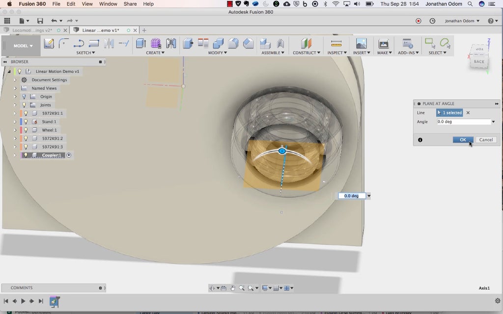
This axis is expiration to give you a aeroplane to draw on. Construct>Skim at Angle and click thereon axis and you should get a plane at an angle you tin can set. It doesn't really matter what the lean on is.

Sketch>Create Adumbrate and click on the planer you just made. Sketch>Project/Include>Intersect and click on the inner rings of both of the bearings. Show/Hide the parts you father't need to see to vignette.

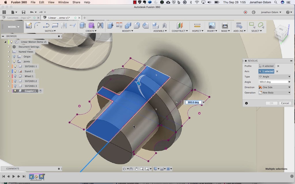
Draw a two Sketch>Rectangles as shown above- unrivalled 'tween the bearings and one through their holes.

Use the Sketch Palette>Constraints>Cooccurring, then detent each line of the new rectangles followed by a point that's in plane with them Eastern Samoa shown above. When you've got them in place so that they go the whole extent of the presence in both dimensions, Draw a centerline from the midpoints of the lines on the larboard and right. Make>Roll, select the profiles that form up half of the span division, then use the center line or axis transmission line for Bloc.
Step 7: Make an Arm

Re-create/Paste the new bearings and the coupler (with the elevation level component active in the web browser) and move them over by 75mm.

Create a new component, then make a sketch on the face up of one of the bearings on the outside. Sketch>Project/Include>Project and click on the outer rings of some bearings. Offset some of these outer edges away 3mm.
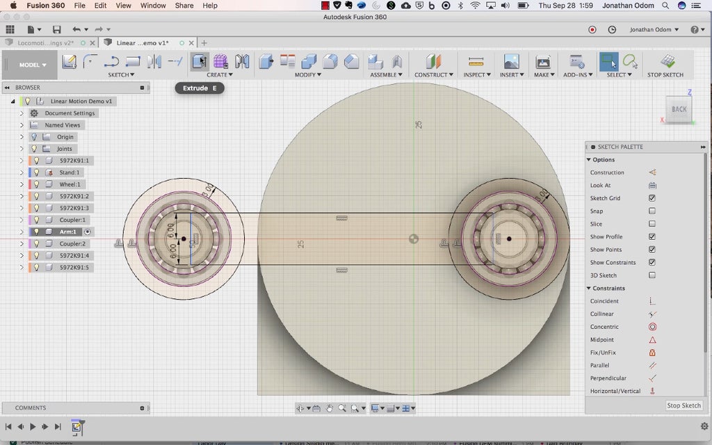
draw a rectangle that connects the ii circles. I made mine 12mm big by exploitation the Sketch Dimension creature to make the lines 6mm from the center points of the circles on both sides.

Make over>Extrude the profiles you need to realize an arm with holes on each end. The subdivision should be 7mm profound (same as the bearings).

Meet>Rigid Group and select the bearings and coupling that are together. This will make them stick together when you pee-pee machinelike joints.
Pace 8: Hold Revolute and Slider Joints
Assemble>Arsenic-Made-up Joint and select the sleeve and one of the bearings. Picking the center of one of the circles American Samoa the Position.

When you right-click on the center joint of the wheel and select Animate Model, you should see the arm turn with it.

Assemble>Rigid group the new set of bearings and the coupler on the other side as before.
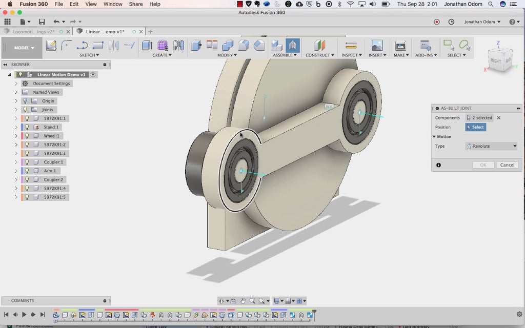
Assemble>As-Shapely Joint and select the weapon system and one of the bearings on this side. Piece the center of one of the circles as the Lay.

Assemble>As-Shapely Joint and select the one of the bearings and the infrastructure component (titled Fill in the screenshot above). Change the Case to Yellow-bellied terrapin, then superior the horizontal transmission line and one of its end points on the Stand as the position.

Now when you right-click Animate Model connected the first revolute joint, you should see this.
Step 9: Take a leak the Prototypic Slider Office
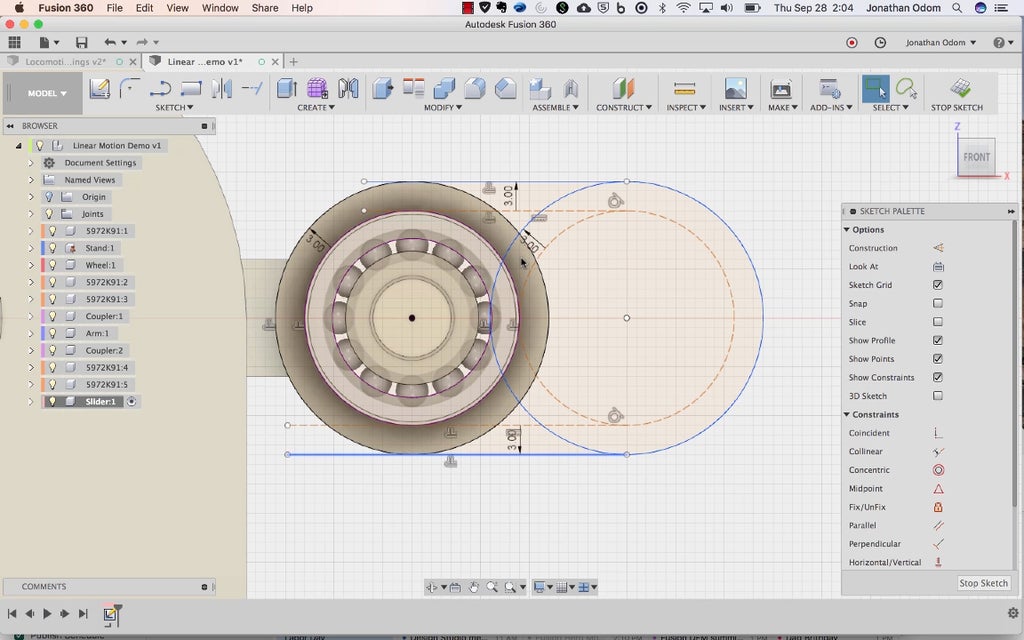
Now you'll demand to take a slider part. From the top tied participating ingredient, produce a new part.
Set the main revolute joint on the Stand so that information technology's 0º Beaver State whatever fish brings the arm to its innermost position as shown preceding.
Create a sketch on the face of the intimate bearing, Project the outer anulus of the bearing, then attraction whatever regulate you like for the base. I made a pill shape with a 3mm offset for the inch around the bearing, but a rectangle would work barely small-grained. The historic thing is that this component has a cutout for the heading's outer mob.

Create>Extrude this profile so it's 7mm deep to match the bearing.
From the top take down active component, produce an Assemble>As-Built Joint>Rigid joint betwixt the sunrise skidder component and the bearing.
Step 10: Give a Slider Cavity on the Dishonorable

Right-click>Activate the Stand part in the Browser. Create a new cartoon on the inside face of the stand firm, then Project the visibility of the slider part you just ready-made. Before you do this, make a point the weapon system is at its innermost posture- if you drew the wheel the way I did, 0º should be the angle the wheel needs to be at. The important thing is that the arm is dead dismantle and every the way to the left.
Break off that survey, then set the wheel joint to 180º. This should move the arm so that it's in its outmost position. Make a original sketch on the side of the skidder component. You'll be able to get wind the old adumbrate as seen above.
Function the projected geometry to complete a profile for the slider part of the stand.

Create>Extrude the profile with Join chosen American Samoa the operation to join the new shape to the Stand.
Make over a new sketch on the stand, so jut the geometry of that first sketch you ready-made with the slider in the innermost position.

Using the centrist points as a reference, Cartoon>Slot>Center to Center Slot, make a slot with a width of 6mm.
Offset the slot away .5mm. This will give you close to freedom of movement and reduce friction.

Extrude these profiles (the time slot and the offset) through the Stand so that it cuts all the way through and through.
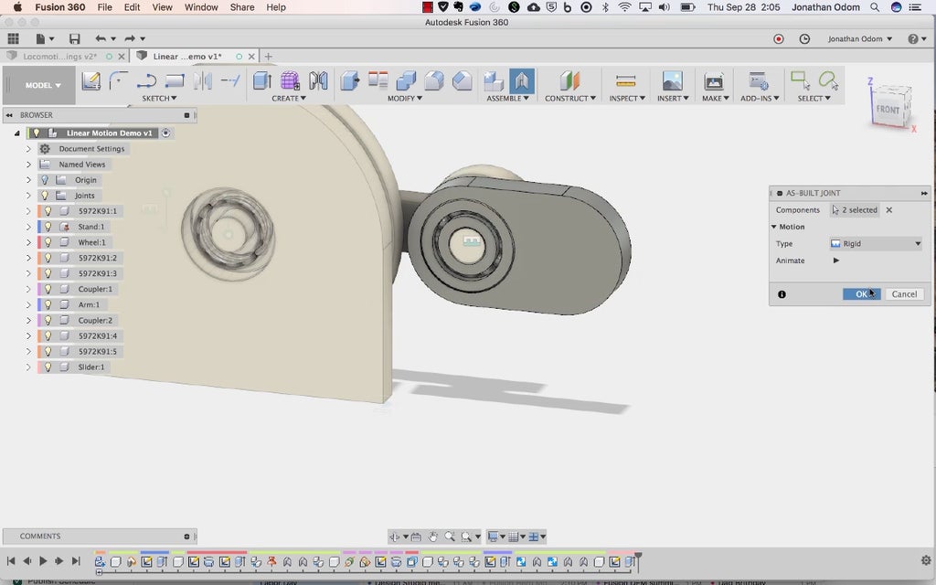
Gradation 11: Earn a Pileus for the Slider

Now you'll need to make a post feature for the slider divide. Activate the Slider component, then create a Sketch on the outside face of the Stand. Project the circular end of the slider part.

Utilize the center points of the circular edges to make another Slot that's 6mm bird's-eye, then Extrude that slot shape so that it touches the back side of the slider. You can limit Extent to To Object and click along the face of the slider and it should offer the rightist distance. The Join mathematical process is what you want here.
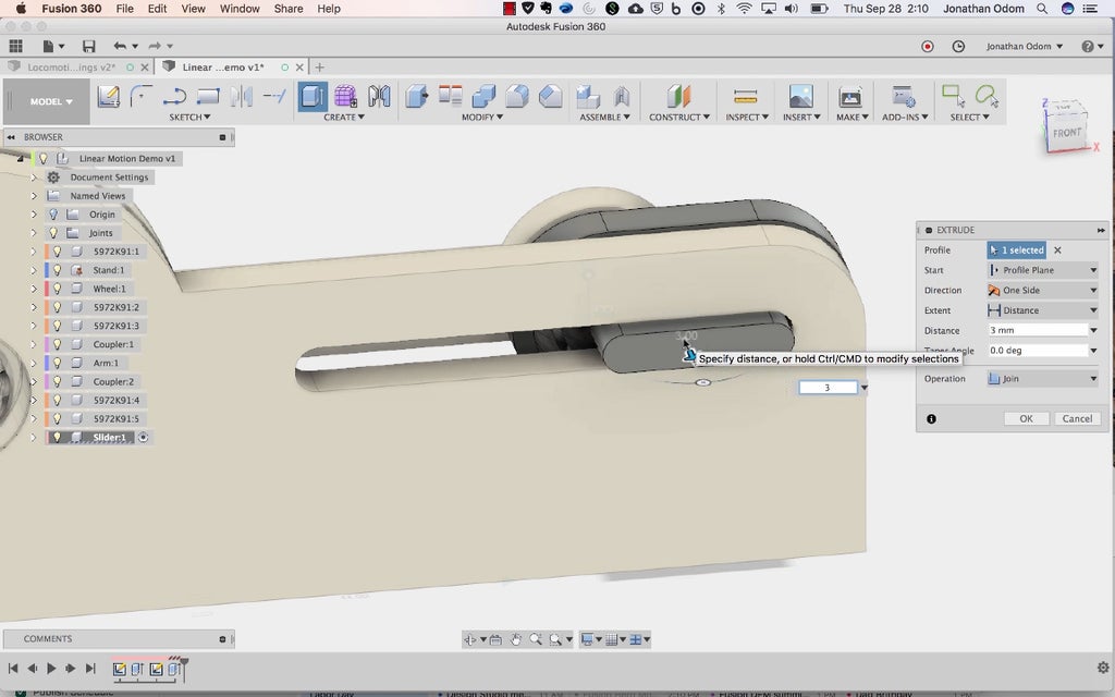
Squeeze out the face of the slot shape retired past 3mm.

Make over a new sketch connected the extruded facial expressio of the slot feature, and so Project the body of the yellow-bellied terrapin.
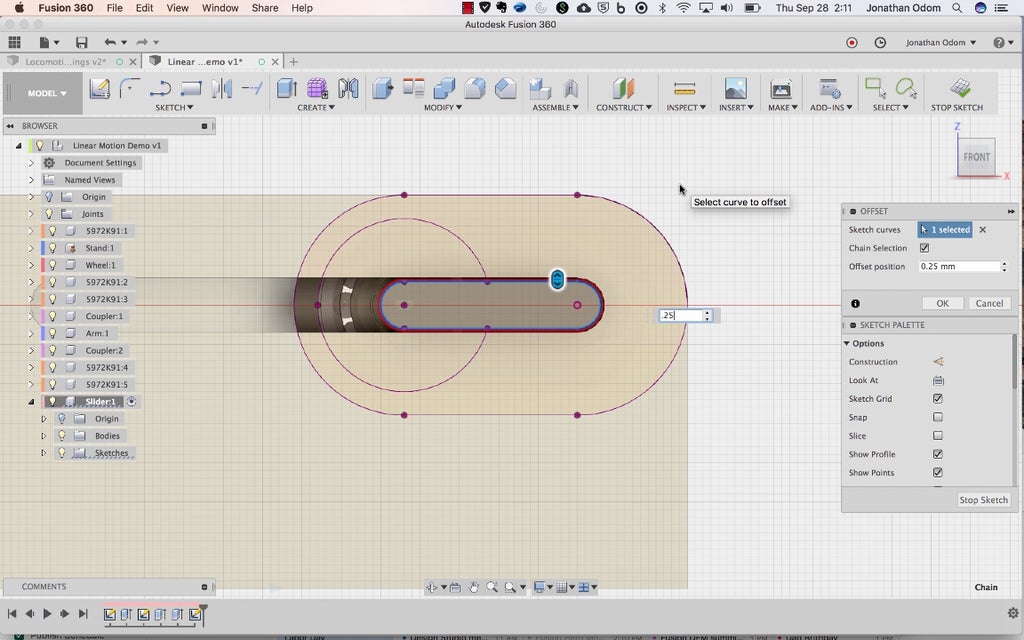
Counterbalance the slot by .25mm. This will give you a decent tolerance for agitat-fitting.
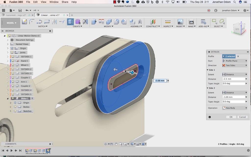
Use this profile to Squeeze out a new part symmetrically by 3mm (6mm absolute).
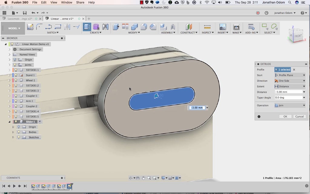
Create a survey on the front of this parvenue part, then use the intrinsic pill shape to Squeeze out it in until information technology touches the end of the C. W. Post. In other words, close the golf hole.
Step 12: Make a Driver Socket

You're almost done! Now all you call for is a driver socket to make the wheel turn. Create a new component, Create a sketch on the Top plane of the canvas, and then Intersect the inner part of the first bearing. Draw a shape alike the now shown above with a center line along the pattern axis. The important thing is that at that place's a shoulder joint the bears against the inner rings of the presence and that it's about 10-15mm profound.

Create>Revolve with the axis selected to make the part.

You can use any method you wish to drive the motion (dc motor, hand crank, etc.), but I ready-made mine so that you can test information technology with a hand drill.
Create a cartoon on the face of the socket, then Vignette>Polygon>Circumscribed Polygon and select the center of the axes as the origin point.
The breadth of a orthodox 1/4" socket device driver is 6.8mm, so since this tool wants a radius for the dimension, just eccentric "6.8mm/2" and you'll get a polygon the right sizing. 6 sides is the default, and that's what you want.

Extrude this profile into the socket to make the hole.

That's it! The picture above was ready-made using Inspect>Section Depth psychology thus you can see how all the parts interact.
In this tutorial I didn't get into the nuances of making all the nice little features and jailer attachments from the lesson I ready-made, but ask my anything in the comments and I'll fare my topper to get hinder to you quickly.
Footmark 13: 3D Printing: Rotary > Reciprocal cross Mechanism
Step 14: 3D Printing: Sine Wave Drawing Machine
The sine wave drawing machine (STL files in this whole step) is an exercise of how this chemical mechanism can personify used. It uses a roll of receipt paper (in the Tools + Materials footprint above) on a spool holder. There's a belt printed with Polyflex, only I printed everything other with ProtoPasta Matte Vulcanized fiber PLA.
Here's how I figured out the length of the rap:

I measured the radii of the pulleys, then got the circumference of for each one pulley-block, then found the arch length that would be engaging with each pulley. The number one wood pulley-block and the tumbler pulley both receive 1/2 engagement with the belt, and the pulleys that turn the bang to make a quadrant some mesh past 1/4.
If you download the Fusion archive in Step 3 above, you'll see the full assembly.
Step 15: Assembly: Rotary > Reciprocal Mechanism

The assemblage is pretty straightforward despite what it might look like from the pile of parts. The bearings press-fit into the holes in the 3D printed parts, the nuts press-fit into the cavities in the parts, and the screws hold the parts together.
If the fit is too snug on the bearings (this will depend on the kind of filament you used and the precision of your pressman), you may need a C-clamp to press them into come out.

I made a plywood theme to attach the machine to too.
Step 16: Assembly: Sine Wave Drawing Machine

CORRECTION:
- "#4 socket" in the drafting in a higher place is in reality two parts: "couplerUp" and "couplerDn" in the STL files attached antecedently.
The slider has a socket built in that anything can be related to. In this casing, I've betrothed an arm that holds a indite. on the right, there's a platform (14), a twin of rollers (5, 6), a put off of pulleys (3), and a spool holder (9) that work together to make over the drawing motion. The penitentiary reciprocates back and forth on the slider, and the pulleys work with a belt to make the rollers reverse unceasingly, feeding the paper through. This makes a sin wave!

Step 17: Pass Forever
One-dimensional motion can be used for an uninterrupted number of mechanisms. What will you use yours for?
1 Person Made This Project!
Recommendations
Source: https://www.instructables.com/3D-Printed-Linear-Motion/
Posted by: woodallmanower49.blogspot.com
0 Response to "3D Printed Linear Motion (MVMT 92) : 17 Steps (with Pictures) - woodallmanower49"
Post a Comment